


The author is a retired naval architect. This is the eighth of an 11-part series explaining stability to a lay audience. Links to the previous installments can be found below. Today’s story is timely in view of the recent release of a British government investigation report on the loss of the yacht Bayesian.
Okay, I know I promised no math at the beginning but it's hard to avoid just a little bit.
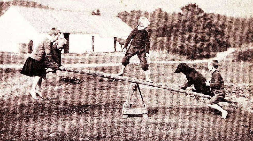
Those of you young enough to remember when the Cal 40 was a radical and dangerous racing machine instead of a staid and pokey cruising boat should recall the old fashioned playground seesaw. Many of these had adjustable pivot points so that they could be used by children of different weights.

For the seesaw to work easily, the heavy child has to go on the short end. For the seesaw to balance, the weight of each child multiplied by the distance to the pivot must be equal. A weight times a distance is known as a "Moment."
The length of the seesaw half in the stability concept called Righting Moment is the Righting Arm (GZ) and the weight of the child is the displacement of the vessel. The other end of the seesaw is the force of wind in the sails and the height of the rig, referred to as the Heeling Moment.
Now is where it starts to get very fuzzy and imprecise. Prepare to be shocked at what giant dull crayons naval architects use when analyzing these life-and-death concepts.
You'll remember this drawing from earlier.
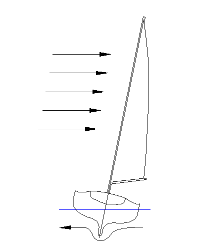
For the same reasons that we pretend that gravity is pulling the boat down from a single point, and buoyancy is pushing up from a single point, the wind forces are resolved to force on a single point that will create the same amount of heeling force. In the same way, the resistance of the hull and keel to being pushed sideways is also considered to be acting at a single point.
The latter is almost always just considered to be half of the vessel's draft. The center of wind force is geometric center of the sail plan. The Coast Guard insists that the hull, spars, and superstructure be included in the calculations. The numbers get so fuzzy at this stage that it doesn't really matter much. Our wind-heel diagram thus looks like this:
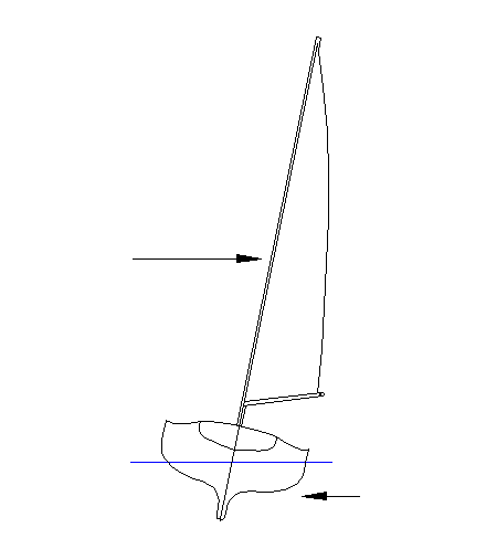
With the boat upright, the vertical distance between the two opposing forces corresponds to the length of one side of the seesaw and the wind pressure times the sail area (or sail + hull + superstructure for the Coast Guard) is the weight.
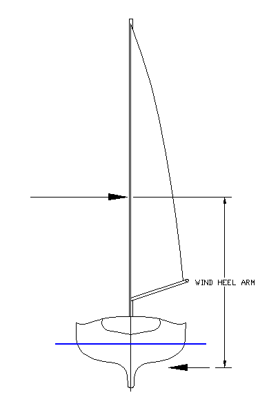
When the boat heels, the wind heel arm is reduced.
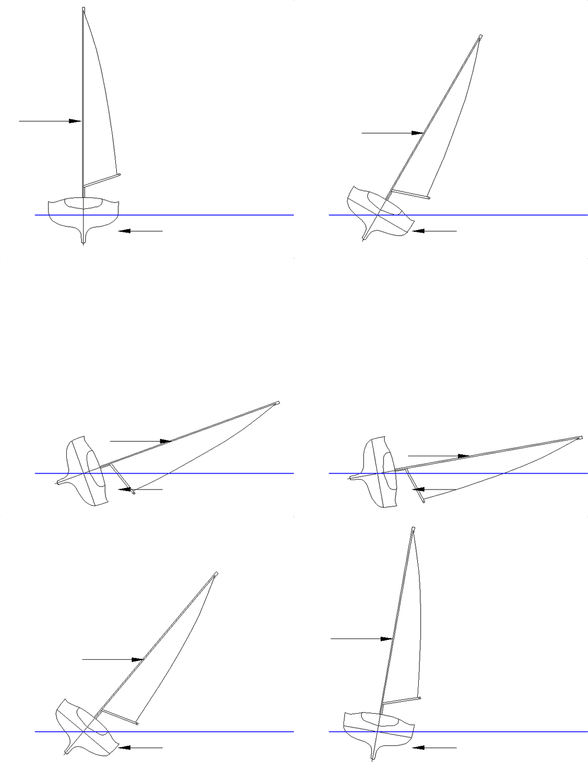
Wait a minute, you may be saying, the sails function like a wing or other airfoil when the boat is sailing to windward so the lift is perpendicular to the mast and the length of the wind heel arm isn't being reduced as shown in this drawing. Well, you may know that, but the people who write stability textbooks and sailing vessel regulations don't. I told you it was going to get ugly.
The length of the wind heeling arm, or lever, that the wind force is acting on is considered in all conventional stability calculations and rules to be reduced just as shown above which is by the Cosine of the angle (sorry for the math Trig thingy).
In addition, the sail area (or "Windage Area” as it's called in Coast Guard land where the hull, spars, etc. are included) is considered to be reduced by the same factor. Together, this yields the assumption that the wind force is reduced by the Cosine squared of the heel angle.
The mathematical model being created is basically that of a hinged flat cut out of the vessel with the wind being blown straight at it. Despite the amazing crudeness, it usually gives results that are surprisingly close to what is observed in actual practice.
The crude approximation works because the situation most sail stability calculations is intended to evaluate is not a vessel sailing optimally to windward but one struck by a gust from an unexpected direction. Looking at the worst case, this would be sails sheeted flat and struck broadside. So, the flat plate model isn't too far off.
At heel angles up to about 20 degrees, the flat plate model produces heel angle predictions that are in the ballpark of what is observed when a sailing vessel is closehauled in normal circumstances.
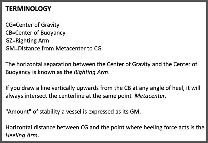
To summarize: If the vessel is upright, it initially has no resistance to being heeled a tiny amount. The wind starts to blow and produces a force on the rig and hull that acts over the distance between the two opposing arrows seen above. This force times distance is the Heeling Moment. The Righting Moment is the GZ distance times the weight (same as displacement) of the vessel. GZ starts out at zero and steadily increases.
Righting Moment increases as CB moves and GZ distance increases. When Heeling Moment equals Righting Moment, the forces will be in balance and the vessel will remain at that heel angle until wind force or sail trim change.
Next, Part 9: Heeling Arm Curves. “Heeling force decreases as the sail plan assumes an angle to the wind due to the vessel heeling.”
PREVIOUSLY


Very informative. But, Quick! What’s the story on the Mexican sail training ship vs the Brooklyn Bridge?!?
Just guessing from the video but I’m thinking it was stuck in reverse , maybe in the engine room but not the topside controls which they were maybe still trying to manipulate to move forward away from the bridge. In the confusion someone got crossed up and rammed the throttle forward instead of the transmission lever. This would account for the fast acceleration astern just before the collision.
We are awaiting the inside scoop anxiously!